Analysis of common problems in on-site HVAC system installation
About air duct production and installation
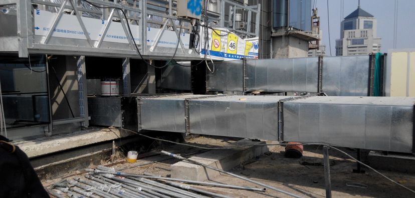
Problem 1: There are no protective casings or the protective casings are too thin in fireproof and explosion-proof walls and floors
Reason analysis: It is believed that the thickness of the casing does not matter much, so in order to reduce costs, the remaining material is between 0.75-1.2MM.
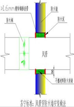
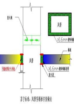
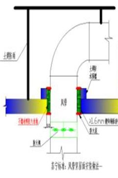
Corrective measures: Strictly implement the mandatory provisions of Article 6.2.1 of GB50243. When the air duct passes through a fire-proof or explosion-proof wall or floor that needs to be closed, the pipe or protective casing should be embedded, and the thickness of the steel plate should not be less than 1.6MM. The space between the air duct and the protective casing should be sealed with non-combustible and non-hazardous flexible materials. Before construction, it is necessary to combine the installation and civil engineering drawings to determine which walls and floors in the project have fire protection requirements and need to install protective casings, and cooperate with pre-embedding during the construction of civil structures.

How to pass through the firewall

How to penetrate the floor slab

How to get out of the roof

Problem: The length or area of one side of the air duct is larger than the specification, and no reinforcement measures are taken, resulting in vibration and noise during operation.
Reason analysis: It is believed that the edges of the air duct or the cross-sectional area have no direct impact on the operation, so the construction unit considers cost savings and cutting corners.
Corrective measures: Article 4.2.10 of GB50243-2002 should be followed: the side length of the rectangle is about 630MM, the side length of the insulated air duct is greater than 800MM, the pipe section is greater than 1250mm or the area of the low-pressure air duct is greater than 1.2M2, and the medium and high-pressure air duct is greater than 1.0M2, all should be taken Reinforcement measures.
When the diagonal length of the air duct is <1500mm, use 2 angle steels and 2 tie rods to fix the air duct. The air duct is fixed on the angle steel with bolts, solid rivets or self-tapping screws; when the diagonal length of the air duct is ≥1500mm, the air duct All sides are fixed with angle steel, and the air duct is fixed to the angle steel corresponding to the long side of the air duct with bolts, solid rivets or self-tapping screws.
The spacing between brackets is 4.56m, which is greater than 3m (standard requirements).
Problem: The quality of the air duct soft connection installation.
Reason analysis: The applicable conditions for soft connection materials used in ordinary ventilation systems and fire prevention and smoke exhaust systems are confusing, and on-site management is not in place.
Corrective measures: The flexible short pipe of the smoke exhaust system must be made of non-combustible materials; it must not be made of ordinary canvas, and should be made of silicon titanium or glass fiber soft joints (non-combustible tests are required).
The glass magnesium air duct and the fan should be connected by flexible short tube
Compensation measures should be taken when air ducts pass through building deformation joints. The picture shows: flexible short pipes made of “three-proof cloth” and connection methods for air supply and exhaust ducts
The air conditioning fan and the air duct should be connected by flexible short tubes. The flanges on both sides should be parallel and not misaligned. The distance between the short tubes should be between 150 and 300mm
The flexible short pipe of the smoke exhaust duct should be made of non-combustible materials
The corners were not handled properly when making the air duct
The distance between the air duct connecting bolts is less than 150mm, the thickness of the sealing gasket is not less than 3mm, the direction of the bolts is consistent, and the length of the nut is 2-3 buckles.
About the installation quality of air conditioning water system
Problem: Pipe welding problem.
Cause analysis: The pipeline is misaligned, there is no gap between the pipes, the gas-cut blanking end of the pipe is uneven, the gap width is incorrect or the bevel is not made, making the pipe difficult to weld through, and the welding slag is not cleaned in time after the pipe is welded, and the welding slag is directly painted with anti-rust paint.
Corrective measures: Pipe welding should be carried out in accordance with Article 9.3.2 of GB50243: the combination and groove form of the pipe butt weld joints should comply with the following table; the straightness of the butt joints should be 1/100, and the total length should not be greater than 10MM. The fixed welding joint of the pipeline should be far away from the equipment and should not coincide with the center line of the equipment interface. The distance between the pipe butt weld and the supports and hangers should be greater than 50mm.
(GB50738-2011 “Construction Specifications for Ventilation and Air Conditioning Engineering” Article 11.2.5.3: The distance between the pipe interface weld and the edge of the support and hanger shall not be less than 100mm).
Problem: The installation of equipment piping supports and hangers in the computer room is unreasonable.
Cause analysis: The equipment piping supports and hangers in the refrigeration machine room are unreasonably set up, and the chilled water pipe supports are not equipped with measures to prevent cold bridges.
Corrective measures: Generally, civil installations are not designed with support and hanger load-bearing supports and hanger processing and installation drawings. Preventive measures: Usually the pipelines in the computer room are suspended from the horizontal main pipe, and the horizontal three-head opening is connected to the ground equipment.
Correct approach: When DN150 ≤ vertical air-conditioning water pipe diameter < DN250, there are 2 fixed wings; when the vertical air-conditioning water pipe diameter ≥ DN250, there are no less than 4 fixed wings, and the insulated water pipe needs to be treated with anti-cold bridge. The method is shown in the picture.
Vertical laying of chilled water pipelines, production and installation of load-bearing brackets, the distance between the casing and the pipeline in the picture must be greater than the thickness of the pipeline insulation layer
Floor supports and accessories should be welded with reinforcing plates
Floor-standing brackets should be installed at the fittings of large-sized chilled water pipes. The insulating thermal rubber pads and steel plates of the brackets should be flush with each other and have a smooth surface
Problem: There is no water seal on the condensed water of the air conditioning unit, and there is a lot of water in the room when it is shut down.
Cause analysis: The water seal is not set according to the design requirements. There is negative pressure in the water accumulation pan, and the water seal height should overcome the negative pressure height.
Corrective measures: The water seal height of the condensate discharge pipe of the air conditioning unit should meet the drainage requirements. For example, the fan pressure is 800Pa and the condensate pipe diameter is 50mm, H1>800/10+50=130mm, H2>800/10/2+50=90mm.
Floor mounted combined air handling unit:
1. The condensation water drainage pipe in the surface cooling section should be equipped with a water seal. The water seal height is greater than the wind pressure to facilitate the discharge of condensation water and prevent internal air from the machine room from entering the unit (measures must be taken to prevent the condensation water from drying up and causing air backflow in winter).
2. The floor of the computer room on the floor should be waterproofed.
Problem: The thermometer setting selection is unreasonable and the temperature test value is inaccurate.
Cause analysis: Incomplete understanding of the drawings and random construction on site.
Corrective measures: Use a bimetal dial thermometer and set it up nearby.
Problem: The connection point between the expansion tube on the expansion water tank and the system pipeline is not set up near the suction inlet of the circulating water pump as shown in the drawing, causing “cavitation” in the water pump.
Cause analysis: Incomplete understanding of the drawings and random construction on site.
Corrective measures: The main principle for selecting constant pressure points is to ensure that there is no negative pressure or vaporization at any point in the system. In the air-conditioning water system, the fixed pressure point is determined, that is, the minimum operating pressure of the fixed pressure point should ensure that the pressure at the highest point of the system is above 5kpa, and should be connected to the suction port of the water pump.


